USB wiring diagrams are essential for understanding connections between devices. They provide visual representations of cable pinouts, enabling proper setup and troubleshooting. These diagrams are crucial for engineers, DIY enthusiasts, and technicians working with USB interfaces, ensuring reliable data transfer and power delivery. Official USB wiring diagram PDFs offer detailed schematics, making them indispensable resources for designing, repairing, and modifying USB connections.
1.1 What is a USB Wiring Diagram?
A USB wiring diagram is a visual representation of the internal connections within a USB cable or connector. It illustrates how wires are connected, detailing pin configurations, wire colors, and their functions. These diagrams are essential for understanding how power and data signals are routed, aiding in installations, troubleshooting, and repairs. They are widely used by engineers, technicians, and DIY enthusiasts to ensure proper connectivity and functionality. Official USB wiring diagram PDFs are reliable resources for accurate schematics.
1.2 Importance of USB Wiring Diagrams in Electronics
USB wiring diagrams are crucial for ensuring proper connectivity and functionality in electronic devices. They provide a clear understanding of cable pinouts, enabling engineers and technicians to design, troubleshoot, and maintain USB interfaces effectively. These diagrams are essential for identifying power and data lines, preventing short circuits, and ensuring compliance with USB standards. They also aid in diagnosing issues like data transfer problems or power delivery faults, making them indispensable for both professionals and hobbyists working with USB technology.
Types of USB Connectors and Their Diagrams
USB connectors include USB-A, USB-B, Mini, Micro, and USB-C, each with unique pin configurations. Their diagrams illustrate power, data, and ground connections, essential for electronics projects and repairs.
2.1 Standard USB-A Connector Pinout
The standard USB-A connector features four pins, with specific functions; Pin 1 serves as the positive voltage (VCC), Pin 2 as data positive (D+), Pin 3 as data negative (D-), and Pin 4 as ground (GND). This configuration ensures reliable power delivery and data transfer. USB wiring diagrams highlight these connections, aiding in cable assembly and troubleshooting. The USB-A pinout is widely used in devices, making it a fundamental reference for engineers and technicians working with USB interfaces.
2.2 USB-B Connector Wiring Diagram

The USB-B connector, commonly used on peripheral devices, features a square-shaped design. Its wiring diagram includes four pins, with Pin 1 as VCC, Pin 2 as D+, Pin 3 as D-, and Pin 4 as GND. This configuration supports both power and data transmission. USB-B diagrams are essential for repairing or modifying cables, ensuring compatibility with devices like printers or older USB versions. Engineers and DIY enthusiasts rely on these schematics for precise connections and troubleshooting.
2.3 Mini and Micro USB Connector Pin Configurations
Mini and micro USB connectors are smaller alternatives to standard USB types. The mini USB has five pins, while the micro USB features five pins in its mini version and ten pins in the micro-B 2.0. These connectors support both data transfer and power delivery. Their compact designs make them ideal for mobile devices. Wiring diagrams for these connectors detail pin assignments, ensuring proper connections for charging and data synchronization. Engineers use these diagrams to design compatible peripherals and repair faulty cables efficiently.
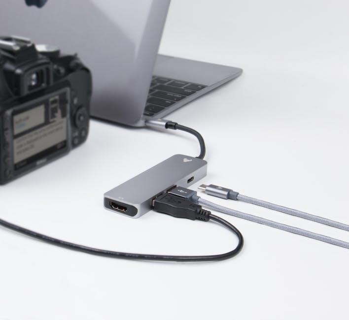
2.4 USB-C (Type-C) Connector Diagram and Pinout
USB-C, or Type-C, is a versatile, reversible connector with 24 pins. Its compact design supports USB 3.2, USB 4, and Thunderbolt 3/4, offering high-speed data transfer and power delivery. The pinout diagram shows pins assigned for power, data, and alternate modes like DisplayPort and MHL. It supports up to 100W of power, making it ideal for charging laptops and devices. USB-C’s pin configuration ensures backward compatibility and flexibility, while diagrams help engineers design and troubleshoot USB-C connections effectively.

Understanding USB Wiring Colors and Their Functions
USB wiring colors follow standardized codes for easy identification. Red is power (VCC), black is ground (GND), green is data positive, and white is data negative. These colors ensure consistent connections, simplify troubleshooting, and prevent wiring errors. Diagrams in USB wiring PDFs highlight these color codes, aiding technicians in installing and repairing USB cables effectively.
3.1 Color Coding Standards for USB Cables
USB cables follow strict color coding standards to ensure reliability and simplicity. The red wire represents power (VCC), while the black wire is ground (GND). Green signifies data positive (D+), and white is data negative (D-). These standardized colors help technicians and users identify connections quickly, reducing errors. USB wiring diagram PDFs often highlight these color codes, making it easier to understand and work with USB cables for installations, repairs, or custom projects. This consistency is vital for maintaining proper functionality and safety in USB connections.
3.2 Red Wire: Power (VCC)
The red wire in a USB cable is designated for power delivery, carrying a voltage of 5V DC. It connects directly to the power source and supplies energy to connected devices. USB wiring diagrams PDFs emphasize the red wire as the primary VCC line, essential for charging and powering peripherals. Proper identification of this wire is critical to avoid short circuits and ensure safe operation. Always refer to USB wiring diagrams to confirm connections before modifying or repairing cables.
3.3 Black Wire: Ground (GND)
The black wire in a USB cable serves as the Ground (GND) connection, essential for completing the electrical circuit. It ensures safe operation by providing a path for excess current and preventing electrical shocks. Proper grounding is critical for both power delivery and data transmission integrity. USB wiring diagrams highlight the black wire’s role in connecting the metal shielding of the cable to the device’s chassis, enhancing signal quality and protecting against electromagnetic interference. Always consult USB wiring diagrams to verify GND connections before performing any modifications or repairs.
3.4 Green Wire: Data Positive (D+)
The green wire in a USB cable is designated as the Data Positive (D+) line, responsible for transmitting data signals. It works in tandem with the white wire (D-) to facilitate communication between devices. USB wiring diagrams emphasize the green wire’s role in differential data transmission, ensuring accurate and efficient data transfer. Proper connection of the D+ line is vital for maintaining signal integrity and preventing data corruption, making it a critical component in USB cable functionality and reliability.
3.5 White Wire: Data Negative (D-)
The white wire serves as the Data Negative (D-) line in USB cables, complementing the green Data Positive (D+) wire. Together, they form a differential pair for data transmission, ensuring reliable communication between devices. USB wiring diagrams highlight the white wire’s role in maintaining signal integrity by providing a return path for data signals. Proper termination and shielding of the D- line are essential to minimize interference and ensure high-speed data transfer, making it a key component in USB connectivity and functionality.
USB Wiring Diagram Explained
A USB wiring diagram illustrates the internal connections of cables and connectors, showing pin assignments, power lines, and data transmission paths. It helps in understanding how USB devices communicate and transfer data, ensuring proper connections for reliable functionality. These diagrams are vital for troubleshooting and custom projects, providing a clear visual guide to USB cable assemblies and their configurations.
4.1 Pin Assignments for Standard USB 2.0
In a standard USB 2.0 connector, Pin 1 is assigned to VCC (power supply), Pin 2 to D- (data negative), Pin 3 to D+ (data positive), and Pin 4 to GND (ground). This configuration ensures proper communication and power delivery between devices. The pin assignments are standardized to maintain compatibility across all USB 2.0 devices, enabling reliable data transfer and power supply. Understanding these pin functions is crucial for designing and troubleshooting USB circuits and connections.
4.2 USB 3.0 Pin Configuration and Wiring
USB 3.0 introduces a 9-pin configuration, adding SuperSpeed pins to the standard USB 2.0 layout. Pins 1-4 remain VCC, D-, D+, and GND, while pins 5-9 handle SuperSpeed operations. The additional pins enable faster data transfer rates, supporting up to 5 Gbps. This enhanced wiring allows for simultaneous data and power delivery, improving performance for high-speed devices. The USB 3.0 pinout is backward compatible with USB 2.0, ensuring versatility across devices.
4.3 Voltage and Current Ratings in USB Wiring
USB wiring operates at a standard voltage of 5V DC, with maximum current ratings varying by version. USB 2.0 and 3.0 devices typically draw up to 500mA, while USB 3.1 can deliver up to 3A. Proper voltage and current management ensure safe and efficient power delivery, preventing overheating or damage. Adhering to these ratings is critical for device compatibility and longevity, as specified in official USB wiring diagram PDFs to maintain reliability and performance across all connections.
4.4 Data Transmission and Signal Integrity
Data transmission in USB wiring relies on the D+ and D- lines for differential signaling, minimizing noise interference. Proper shielding and twisted pairs ensure signal integrity, especially in high-speed USB 3.0 and 3;1 connections. Wiring diagrams in official USB PDFs specify correct termination and routing to maintain data reliability. Signal degradation can occur due to poor connections or excessive cable length, highlighting the importance of adhering to standards for optimal performance and error-free communication.
4.5 Grounding and Shielding in USB Cables
Proper grounding and shielding are essential for reliable USB operation. The GND wire provides a safe path for electrical currents, preventing shocks and noise. Shielding in USB cables protects data lines (D+ and D-) from electromagnetic interference (EMI). This ensures stable data transmission and prevents signal degradation. USB wiring diagrams in official PDFs emphasize correct grounding techniques and shielding materials to maintain data integrity and device safety, especially in high-speed applications.
Step-by-Step Guide to Reading a USB Wiring Diagram
Learn to identify connectors, understand pinouts, and interpret wire colors. Use official USB wiring diagram PDFs to decode layouts for repairs, DIY projects, or custom cable assembly.
5.1 Identifying the Connector Types
Identifying USB connector types is crucial for understanding wiring diagrams. Common types include USB-A, USB-B, mini, micro, and USB-C. Each has a distinct shape and pin configuration. Referencing official USB wiring diagram PDFs helps distinguish these connectors. USB-A is rectangular, while USB-B is square. Mini and micro connectors are smaller, with micro being the thinnest. USB-C is reversible and compact. Correct identification ensures proper cable assembly and functionality, avoiding errors in projects or repairs.
5.2 Understanding Pin Numbering
Understanding pin numbering is essential for interpreting USB wiring diagrams. Pins are numbered sequentially, with specific functions assigned to each. For example, pin 1 is typically VCC (power), pin 2 is D- (data negative), pin 3 is D+ (data positive), and pin 4 is GND (ground). This standardized numbering helps in identifying connections quickly. Referencing USB wiring diagram PDFs ensures accuracy, as they provide detailed tables and visual layouts for various USB versions, such as USB 2.0, 3.0, and Type-C, aiding in precise cable assembly and troubleshooting.
5.3 Interpreting Wire Colors and Their Functions
Interpreting wire colors is crucial for understanding USB wiring diagrams. Standard USB cables use color coding to identify wire functions: red for power (VCC), black for ground (GND), green for data positive (D+), and white for data negative (D-). These colors help in quickly identifying connections and ensuring proper wiring. USB wiring diagram PDFs often include legends or tables to clarify color functions, making it easier to assemble or repair cables accurately and safely, avoiding potential short circuits or data transmission issues.
5.4 Recognizing Power and Data Lines
In USB wiring diagrams, power lines (VCC) and ground (GND) are essential for voltage supply, while data lines (D+ and D-) handle communication. Power lines are typically red (VCC) and black (GND), ensuring proper voltage delivery to devices. Data lines, often green (D+) and white (D-), facilitate data transfer between devices. Recognizing these lines is critical for maintaining proper functionality and safety, preventing short circuits or data corruption. USB wiring diagram PDFs clearly label these lines to help users identify and connect them accurately.

Common Applications of USB Wiring Diagrams
USB wiring diagrams are widely used for charging devices, data transfer, and DIY electronics projects. They also aid in custom cable assembly and device manufacturing processes effectively.
6.1 Charging Devices (Phones, Tablets, etc.)
USB wiring diagrams are essential for safely charging devices like smartphones and tablets. They ensure proper connections between power (VCC) and ground (GND) wires, preventing short circuits. By identifying the correct pin configurations, users can achieve efficient charging. These diagrams are particularly useful for DIY projects or repairs, ensuring compatibility and optimal performance. They also help troubleshoot charging issues, making them indispensable for both casual users and technicians working with USB-based charging systems.
6.2 Data Transfer Between Devices
USB wiring diagrams play a critical role in enabling reliable data transfer between devices. They clarify the connections for data-positive (D+) and data-negative (D-) wires, ensuring proper communication. These diagrams help configure USB-to-UART converters, like CP2102, for programming microcontrollers. They also aid in troubleshooting data transmission issues, such as faulty connections or signal degradation. By following USB wiring standards, users can achieve stable and high-speed data transfers, making these diagrams essential for both simple and complex data exchange applications.
6.3 DIY USB Projects and Repairs
USB wiring diagrams are invaluable for DIY projects and repairs, providing clear guidance for custom cable assembly and connector modification. They help enthusiasts create unique solutions, such as USB-to-TTL converters or custom hubs. Diagrams also aid in diagnosing issues like short circuits or incorrect pinouts. By following these schematics, users can safely repair damaged cables or repurpose connectors, ensuring reliable functionality. This makes USB wiring diagrams essential for both novice makers and experienced technicians seeking to breathe new life into USB devices.
6.4 Custom USB Cable Assembly
USB wiring diagrams are essential for custom USB cable assembly, detailing pin configurations and wire color standards. They enable the creation of cables tailored to specific devices, ensuring proper connections for power delivery and data transfer. Proper shielding and grounding, as shown in the diagrams, maintain signal integrity, crucial for reliable performance in charging, data syncing, and custom hardware integration. This ensures functionality and prevents common issues like short circuits.
Tools and Software for Creating USB Wiring Diagrams
CAD software like AutoCAD and Eagle are used for designing PCB layouts. Fritzing is ideal for DIY projects, while KiCad is a popular open-source option. Online tools like Lucidchart and draw.io simplify diagram creation, making it accessible for both professionals and hobbyists to visualize and document USB wiring configurations effectively.
7.1 CAD Software for PCB Design
CAD software like AutoCAD, Eagle, and KiCad are widely used for designing USB wiring diagrams. These tools allow precise layout creation, ensuring accurate pin configurations and connections. Engineers use them to visualize USB interfaces, such as USB-A, USB-B, and USB-C, and to plan PCBs for devices. Features like schematic capture and simulation help verify designs before fabrication. These programs are essential for creating professional-grade USB wiring diagrams, enabling efficient data transfer and power delivery in electronic circuits and systems.
7.2 Cable Wiring Diagram Generators
Cable wiring diagram generators simplify the creation of USB wiring diagrams by automating the design process. Tools like WireCAD, Circuit Diagram, and online diagrammakers provide templates and libraries for USB connectors, enabling users to easily map pinouts and wire colors. These tools are ideal for both professionals and DIY enthusiasts, offering customization options to suit specific projects. They streamline the process of generating accurate and professional-looking USB wiring diagrams for various applications, from simple charging cables to complex data transfer setups.
7.3 Online Tools for USB Pinout Visualization
Online tools for USB pinout visualization provide interactive and detailed diagrams to help users understand connector configurations. Websites like USB.org, Pinout.xyz, and others offer comprehensive resources for visualizing USB pinouts. These tools often include 3D models, downloadable PDFs, and interactive diagrams that highlight power, data, and ground pins. They are invaluable for engineers, hobbyists, and technicians designing or troubleshooting USB cables. Such tools ensure accurate connections and simplify the process of creating custom USB wiring diagrams for various applications.
Troubleshooting USB Wiring Issues
Troubleshooting USB wiring issues involves identifying faulty wires, checking for short circuits, and verifying voltage levels. USB wiring diagrams provide a clear reference for diagnosis and repair.
8.1 Identifying Faulty Wires or Pins
Identifying faulty wires or pins in USB connections requires careful inspection and testing. Using a multimeter, check for continuity and resistance to detect breaks or short circuits. Visually inspect wires for damage or corrosion. Referencing a USB wiring diagram PDF helps verify correct pin configurations and connections. Faulty pins may show signs of physical damage or incorrect voltage readings. Systematic testing ensures accurate diagnosis and repair of USB wiring issues.
8.2 Checking for Short Circuits
Checking for short circuits in USB wiring involves using a multimeter set to ohms to measure resistance between pins. A short circuit is indicated by unusually low resistance or a direct path between power and ground wires. Consult a USB wiring diagram PDF to verify correct pinouts and ensure no unintended connections exist. Inspect the cable for physical damage or improper soldering, which can cause shorts. Always disconnect power before testing to avoid electrical risks and potential damage to devices.
8.3 Testing Voltage and Current Flow
To test voltage and current flow in a USB wiring diagram, use a multimeter set to DC voltage mode. Place the probes on the VCC and GND pins, as indicated by the diagram. Ensure the device is powered on for accurate readings. For current flow, switch the multimeter to current mode and insert it in series with the circuit. Use a USB current meter for safety and convenience. Always refer to the USB wiring diagram PDF for correct pinouts and safety guidelines to avoid overvoltage or overcurrent issues.
8.4 Diagnosing Data Transfer Problems
To diagnose data transfer issues, inspect the USB wiring diagram PDF for correct D+ and D- connections. Check for short circuits or open wires in the data lines. Use a multimeter to test continuity between data pins and verify proper grounding. Ensure the USB controller and drivers are updated. Examine the host and device configurations for compatibility. If issues persist, consult the USB specifications or replace faulty cables. Proper identification and repair of data line faults restore reliable communication between devices, ensuring efficient data transfer and minimizing errors.

Safety Precautions When Working with USB Wiring
Always avoid electrical shock by disconnecting power before working. Handle USB connectors carefully to prevent damage. Use protective gear and ensure proper grounding to prevent overvoltage risks.
9.1 Avoiding Electrical Shock
Avoiding electrical shock is critical when working with USB wiring. Always disconnect devices from power sources before handling. Use insulated tools and ensure no conductive objects are nearby. Ground yourself to prevent static discharge. Never touch live wires or circuits. If unsure, consult a professional. Proper safety measures ensure safe and effective work with USB connections, preventing potential hazards and injuries.
9.2 Proper Handling of USB Connectors
Proper handling of USB connectors is crucial to ensure reliability and longevity. Avoid inserting connectors forcefully, as this can damage pins or sockets. Always handle connectors by the body, not the pins, to prevent bending or breaking. Use the correct orientation to avoid physical stress. Regularly inspect connectors for dirt or corrosion and clean them gently. Store USB cables in a dry place, away from extreme temperatures, to maintain performance and prevent damage. Proper care extends the lifespan of USB connections and ensures consistent functionality.
9.3 Preventing Overvoltage and Overcurrent
Preventing overvoltage and overcurrent is essential to safeguard USB devices and circuits. Use voltage regulators and fuses to control power flow. Ensure proper wiring as per USB diagrams to avoid short circuits. High-quality components and adherence to USB specifications minimize risks. Incorporate protective circuits like TVS diodes to absorb voltage spikes. Regularly test power supplies during design and implementation. These measures ensure reliable operation and protect against electrical damage, promoting longevity and performance of USB-connected devices.

Resources for USB Wiring Diagram PDFs
Official USB specifications, technical documents, and reputable electronics websites offer free USB wiring diagram PDFs. Books and guides on USB design also provide detailed schematics.
10.1 Official USB Specifications and Documents
Official USB specifications and documents are the primary sources for accurate wiring diagram PDFs. The USB Implementers Forum (USB-IF) provides detailed technical documents, including pin configurations, signal protocols, and compliance guidelines. These resources are essential for engineers and technicians working with USB interfaces. They cover all versions, from USB 2.0 to USB-C, ensuring compatibility and proper implementation. Additionally, application notes and white papers offer in-depth insights, making them invaluable for designing and troubleshooting USB connections.
10.2 Websites Offering Free USB Wiring Diagrams
Several websites provide free USB wiring diagrams in PDF format, catering to technicians and DIY enthusiasts. Platforms like All About Circuits and Instructables offer detailed USB wiring guides, including pinouts and cable schematics. Forums such as EEWeb and Electronics Tutorials also share community-contributed diagrams, useful for troubleshooting and custom projects. These resources are invaluable for understanding and working with USB connections, ensuring compatibility and proper implementation across various devices and applications.
10.3 Recommended Books and Guides
For in-depth understanding, books like USB Complete by Jan Axelson and USB Hardware and Software by John Hyde are highly recommended. These guides provide detailed insights into USB standards, wiring, and implementation. Additionally, textbooks like Learn to Effectively Communicate Your Research Ideas and Applied Informatics textbooks offer practical knowledge for students and professionals. These resources are essential for mastering USB wiring diagrams and their applications in modern electronics and data transfer systems.